Circuit Design
About The Solenoid Circuit
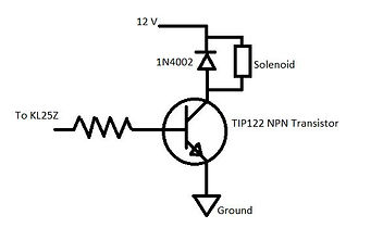
Solenoid schematic


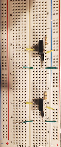
The first photo shown is of the electrical schematic for operating the solenoids, and shows all of the required hardware and how to assemble it. Below that, is the actual circuit. Shown are two separate circuits, both being used to operate separate solenoids. The green wires indicate where the positive connections should be, and the yellow are negative. The electrical circuitry required for the operation of the solenoid valves includes:
-
A solenoid Valve
-
An NPN transistor
-
A snubber diode
-
A 390 ohm resistor
-
An external 12 volts DC power supply
-
A micro-controller
The solenoid valve is the method for directing water flow for the garden. The valve has 2 wires, and while it does not matter what wire is positive or negative for the operation of the valve, it is important to consistently use the same wire for the same purpose every time.
The transistor is acting as the switch that either supplies or cuts 12 volts to the solenoid.
The snubber diode prevents damaging high currents returning back to the transistor. The high current comes from the solenoid valve going immediately shut when power is cut.
The 390 ohm resistor prevents high current from reaching the base pin of the transistor, and keeps from damaging the transistor.
The 12 volts DC is the power needed to operate the solenoid valve.
The micro-controller send the signal to the base of the transistor, telling it to open or shut the solenoid. This is how we control the solenoid.

The image above shows the pinout for the KL25z for the pins I used. All of the pins with a blue dot are the pins used for the moisture sensors. The yellow is for the potentiometer simulating the sun. The green is where the valves were connected. The red is where the servo motor was connected. The pink is where the US was connected, and the pin below it as well.

The image above shows the way to wire the CDS cells and the thermistors. The CDS cells are on the left, and the thermistor is on the right. As you can see, the CDS cells can be wired using either a pull-up or pull-down resistor. What this means, is that the sensor can be wired so that the reading from the microcontroller will increase with n increase in brightness or darkness. The range that this change in value occurs, is entirely based on the resistor chosen. If you choose something too small or high, the range that the sensor can work decreases. For the thermistor, you would want to use a pull up resistor, so the temperature increases with temperature.
Before choosing the right resistor to use, you need to test the resistance of the sensor being used. Then, using Ohm's law, we can determine the best resistance value to give us the best range of values.
The output pin on the circuits shown, is the pin location that you choose to use for the sensor. These reading can either be digital or analog, and there is a big difference. The digital reading will output a voltage reading between 0-5 volts, but the analog reading will display and ADC value. The ADC reading tends to work best for converting the reading to a useable value, due the larger range.


